- HOME
- SAGA Light Source
- User Information
- Beamlines
- BL09 : experimental equipment
BL09 : experimental equipment
X-ray irradiation in LIGA process

Figure 1. X-ray irradiation chamber
Accessories
Horizontal(X) / vertical(Z) / rotation(R) driving stage, Scroll pump, Helium, nitrogen, and argon gases, Mortar controller unit, Vacuum display.
Outline
- The deep micro-fabricated patterning with 0.5 mm-depths is performed.
- The width of the irradiation window of the equipment is around 140 mm. You can bring self-built equipment.
- The driving ranges of the vertical and horizontal stages are ±30 mm and the range of the rotation stage is ±120°.The experiment is performed with driving the stages during the irradiation (see Fig. 2).
- Helium gas is available. Users can conduct the irradiation under the gas atmosphere.
- The irradiation dose is controlled by product of Storage ring current (mA) and Time (hour). (see Fig. 3).
- Please contact us when you have no idea of holding the resist sample.
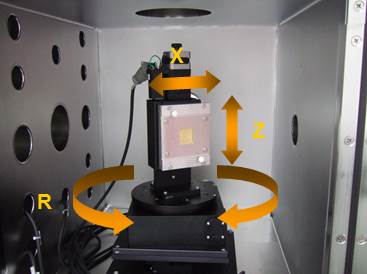 Figure 2. X, Z, R stages in the chamber |
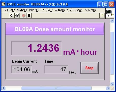 Figure 3. Dose display |
Processing
- Align horizontal, vertical, and rotational axes using fluorescent screen so as to be irradiated on center of stage.
- Fix resist and mask on stage.
- Sample is irradiated with up-and down movement of Z-axis in desired time.
- Sample is irradiated under helium atmosphere if necessary.
Radiation effect

Figure 1. Illustration of experimental condition
Accessories
Horizontal(X) / vertical(Z) / rotation(R) driving stage, Metal filters at tens micrometers (aluminum, copper).
Outline
- X-ray induced mutant breeding is conducted using white X-ray.
- The irradiated doses are needed to estimate before the experiment. The facility staff will calculate doses.
- The wide area should be irradiated owing to driving the Z stage in range of ±25 mm.
- The irradiated time is around ten minutes. In the case of seed of marble size, you will be able to irradiate around 1,000 pieces.
- Please contact us when you have no idea of holding the sample.
 Figure 2. Calculated spectra |
|
.jpg)
Processing
- Hold sample at front of beam and align sample stages so that beam goes through center of sample. Beam path is confirmed by a visible laser.
- Set metal filters with required thickness in front of sample.
- Irradiate the doses with driving Z stage.
X-ray topography

Figure 1. X-ray topography instrument
Accessories
Goniometer, Si channel-cut monochromator, Si-PIN diode, Industrial X-ray film (~2 µm), Flat panel sensor (50 µm), High resolution CCD detector (7 µm), High-temperature heater (<1500 °C)
Outline
- X-ray topography is a diffracted-based imaging technique. The defect structure in a material can be observed.
- The experiments on both of Laue and Bragg geometries can be employed.
- Crystal with thicknesses less than 3 mm can be available for observing defect structure in the case of transmission geometry.
- You can precisely align the axes around the sample. The axes are controlled by LabVIEW programs (see Fig. 3).
- The monochromatic X-ray is also supplied using the switching function of white/monochromatic X-ray.
- The X-ray film has high-resolution and wide-area though development is required. In contrast, the real-time observation is allowed to be performed using CCD detector.
- The high-temperature heater is also equipped. Please inquire the staff when you want to use it.

|
.jpg) Figure 3. Operation program |
Processing
- Adjust slit position and slit size.
- Hold sample on stage.
- Set condition of white X-ray.
- Capture a required diffraction spot using a flat panel sensor.
- Set condition of monochromatic X-ray using a white/monochromatic X-ray switching function.
- Sequentially, in case of applying the monochromatic X-ray, the beam alignment of the monochromator is required.
- Record a high-resolution topograph using an industrial X-ray film or CCD detector.